This week we had to design a circuit that utilized a sensor and digital or analog output/input pins. I decided to use a photo-resistor as my sensor in order to generate values to pass into the Arduino. I first tested to see if the photo-resistor was working by wiring it up and printing the values to the Serial monitor. Once I got a general feel of the indoor range of the resistor, I mapped the values from 0 to 255. I attached this to an LED in hopes that the light would brighten and dim based on the photo-resistor values. The following video shows what happened:
As you can see, the light only turned on and off; no dimming happening. I went through the program and saw nothing wrong with the code, then, I went through the circuit and still nothing seemed out of place. I figured it had to do with the way the output pin was interpreting the analog values, and I tried changing pins…. and POOF! It worked. I noticed that the pin I placed it in had a little squiggly (tilde) after the number and figured it was a pin with pulse width modulation. Here is a video of the dimming working:
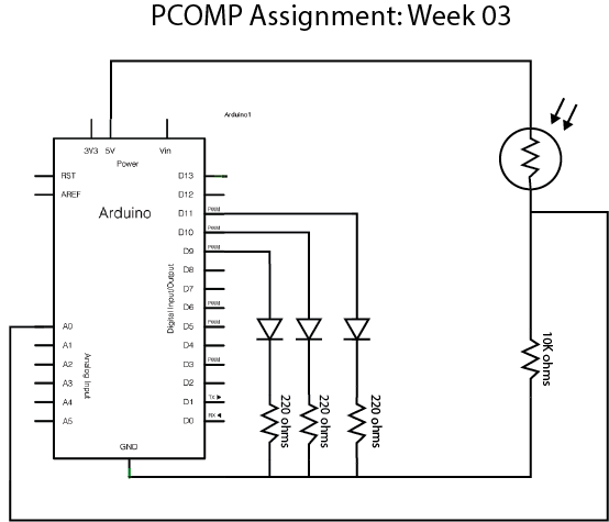
Finally to spice things up a little, I wrote some code and hooked up a circuit that would change an LED based on the light values of the photo-resistor. The schematic and video of it working are shown below:

int lightSensor = A0;
int led_01 = 9;
int led_02 = 10;
int led_03 = 11;

void setup() {
  // put your setup code here, to run once:
  Serial.begin(9600);
  pinMode(led_01,OUTPUT);//blue light
  pinMode(led_02,OUTPUT);// red light
  pinMode(led_03,OUTPUT);// green light
  pinMode(lightSensor,INPUT); // Photo-resistor

}

void loop() {
  // when the photo-resistor reaches a certain value the light will switch from blue to red to green
  int lightValue = analogRead(lightSensor);
  int ledOutput = map(lightValue,800,300,0,255); // converts the range of light values from the photo resistor to analog circuit values
  if(ledOutput <= 80) {// This next bit of code changes which LED is turned on based on the current photro-resistor values
    digitalWrite(led_01, HIGH);
  } else digitalWrite(led_01, LOW);
  if(ledOutput  80) {
    digitalWrite(led_02, HIGH);
  } else digitalWrite(led_02, LOW);
  if(ledOutput  150) {
    digitalWrite(led_03, HIGH);
  } else digitalWrite(led_03, LOW);
  //analogWrite(led,ledOutput);
  Serial.println(ledOutput);

}
Finally, I wanted comment on an interactive experience that I had when visiting the Cooper Hewitt Museum. There was an interactive piece that was there that looked like a giant fur rug had been made into a curved wall. As you touched the rug, the wall would make music from an instrument. The more hands touched the wall, the more instruments would play music and the more it would sound like an orchestra. It definitely worked best when multiple people were touching it however, the music was not playing loudly enough in the space to really get a good feeling oh how your individual actions were affecting the music. The black fur wall was very inviting to touch and almost everybody who would pass by the piece were drawn to it I thought this was a really cool way of exploring touch and sound. Observing the piece from a technical angle, it seems like there are some sort of sensors underneath the fur (whether force or capacitive touch or some other sensor) that receives input and code that tell the piece to output an instrument playing music. If another sensor is triggered, another instrument is added, and so on and so forth. Very creative and not to complex. My kind of art piece!

Unfortunately I was unable to get a good video of the piece; I thought the camera was in video mode, but it just took a picture.